Prusa I3 Half-ring Lights


ameliamariecollins
Full Name
Amelia Marie Collins
| Filename | Downloads | Size | Uploaded | |
|---|---|---|---|---|
| Prusa I3 Light Shell.stl | 3798 | 4.2 MB | on 16/6/20 | Download |
| Prusa I3 Light Reflector.stl | 3804 | 1 MB | on 16/6/20 | Download |
| Prusa I3 Light Clips.stl | 3872 | 434 kB | on 16/6/20 | Download |
| CD3CBB89-09D6-4794-8138-0761581FDA2A.jpeg | 2964 | 323 kB | on 16/6/20 | Download |
| B956E8F3-D2D7-4A81-8946-7162621DB85D.jpeg | 2931 | 296 kB | on 16/6/20 | Download |
| AA10BEA9-8C51-4491-8B60-9074894B1FC7.jpeg | 3002 | 359 kB | on 16/6/20 | Download |
| 83B57C5D-ED1E-42D7-BFE4-EAEAF266FE95.jpeg | 3018 | 397 kB | on 16/6/20 | Download |
| 5BE4AEAC-E58A-4CC2-B779-57DD6461B8B8.jpeg | 2977 | 278 kB | on 16/6/20 | Download |
| CF515E41-6C9C-4894-9BBD-140111176EE0.jpeg | 2972 | 278 kB | on 16/6/20 | Download |
| F0413FDE-2549-4430-BC53-4A753FD7EE4A.jpeg | 2945 | 305 kB | on 16/6/20 | Download |
| 61037B73-CB32-4602-8FE0-D9511E635487.jpeg | 2988 | 262 kB | on 16/6/20 | Download |
| F2B9C1B6-1191-4EA4-BB50-1C79EA230E48.jpeg | 2887 | 237 kB | on 16/6/20 | Download |
| 180E16DF-9926-4786-9A07-720C73528161.jpeg | 3051 | 236 kB | on 16/6/20 | Download |
| 1C953A6F-D7A1-4202-9300-F4016900633A.jpeg | 3058 | 323 kB | on 16/6/20 | Download |
Description
Behold! Clip-on half-ring lights for your Prusa I3! Supply the LED strip and power supply of your own choosing, and with a bit of soldering, you've got gorgeous light to illuminate your print bed.
Instructions
Step 1: Things You'll Need
In addition to the printed parts, you'll need to select an LED strip. It should be the type that can be cut to length has pads on which to solder leads. In addition, you'll need some way to power the LED strip. Many come with their own power supply, and some even have dimming capabilities -- it's up to you. The LED strip should be 10mm wide at the absolute maximum. I purchased an 8mm strip and it fit perfectly.
Needless to say, you'll also need to have some soldering experience. We'll just be soldering wires onto copper pads, so it's nothing tricky, I promise.
Have this stuff ready? Great! Let's build.
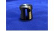
Step 2: Printing the Parts
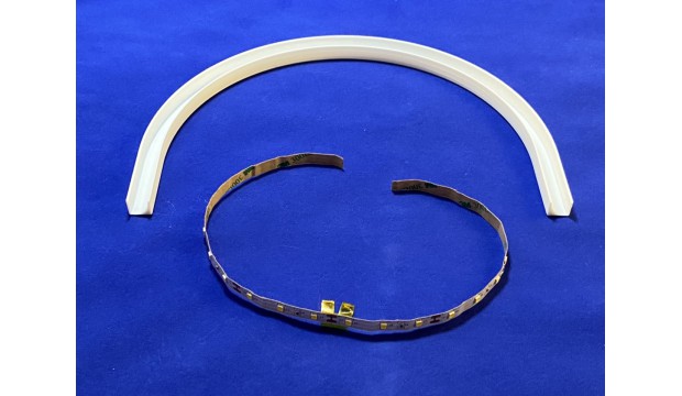
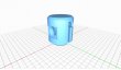
You'll need a pair of each part: two clips, two shells, and two reflectors.
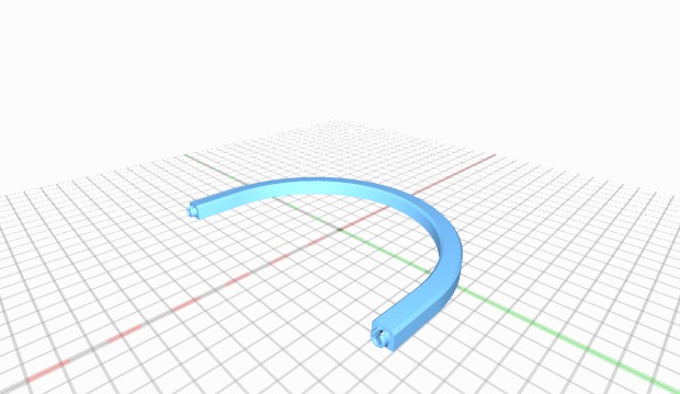
The reflectors should be white or a very light color. This is important because this fixture delivers indirect light, bouncing the LED light off a curved surface inside the reflector. The material chosen will have a strong effect on the color and quality of the light output.
The shell and clip colors are up to you. I chose silk black for my prints, and I think it has a classy, solid look, like machined metal. It goes well with the textured surface of the printer's frame, but there are many options.
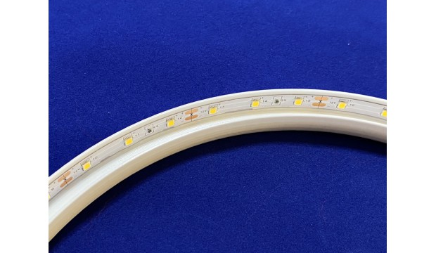
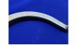
Step 3: Installing the LED Strips Into the Reflectors
Cut two lengths of LED strip to fit the outside, flat wall of each reflector. You may need to cut the strip shorter in order to get and integral number of sections. Apply solder to the pads at both ends of each length to make later assembly easier.
To make it easier to get the LED strip lined up, I used this trick: I gently lifted the backing in the middle of each length, wrapping some tape around the backing it so I could peel it up easily later. I then started from the middle of the reflector, gradually pulling away the backing while pushing the LED strip into place.
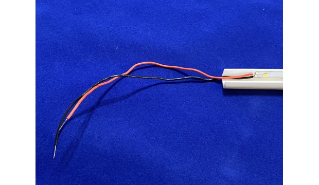
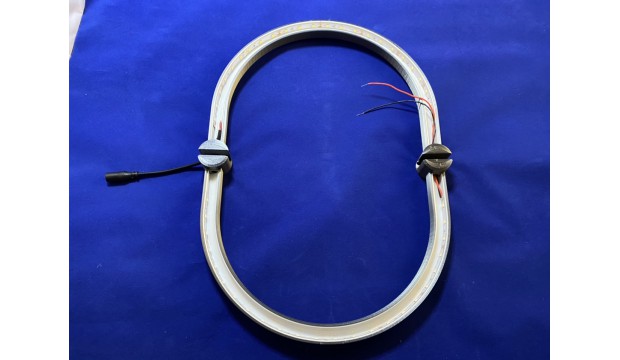
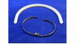
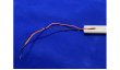
Step 4: The Interconnection Leads
Attach short lengths of wire to one of the end of just one of the LED/reflector assemblies, in the orientation shown. Watch that polarity!
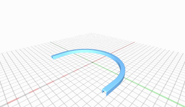
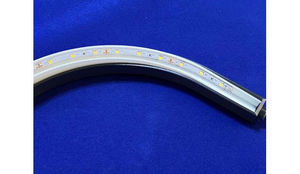
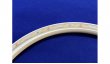
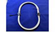
Step 5: Mating the Reflectors to the Shells
Press the reflectors into the shells. The open sides should face the same direction. Push hard, the reflector should be about 1mm below the edge of the shell. Run the leads (of the reflector you soldered leads to) through the port on the back of the shell.
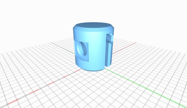
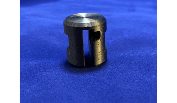
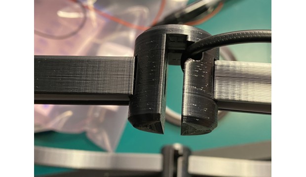
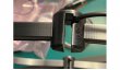
Step 6: Preparing the Right Clip
Note that clips have a little port on one side. This is a channel for the connection to your power supply. This port will go on the BACK side of the top rail. Insert the leads from your power supply through this port and through the socket on the back side of this chip.
Step 7: Assembling!
Push the rear half-ring (the one you soldered leads to) into the sockets in the rear (extra port) side of the clips. The open sides of the reflectors will be facing the slot in the clip. The leads you soldered will feed straight through and out the front socket of the left clip. The incoming power wire will feed through the socket at the rear of the right clip. Push the other half-ring into place.
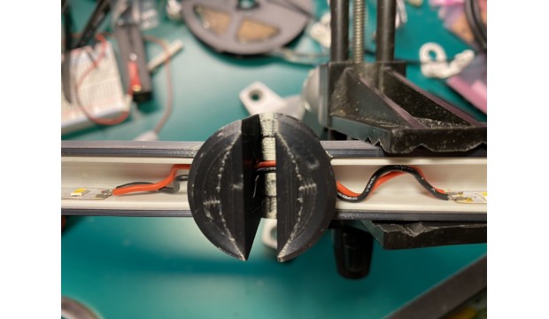
Step 8: Soldering
Solder the incoming power supply wires to the pads on the LED strip. For the interconnection wires, don't pull the wire through tighly, but leave a couple extra centimeters of slack. This will allow the wires to be pushed up into the top of the clip where a channel has been provided to allow the wires to run over the frame. I pushed a roll of tape into the slot to get an idea of length, and then left a bit of slack. Watch that polarity!
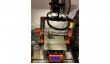
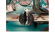
Step 9: Placement and Testing
Place the assembly over the top of the printer frame with the incoming cord in the right. Make sure the cord stays neatly in the port. Push the assembly down until it's fully seated on the frame. Apply power and enjoy!
License
Attribution - Non-Commercial - Share Alike
Comments
Sign in to add a comment.